Raft Geometry
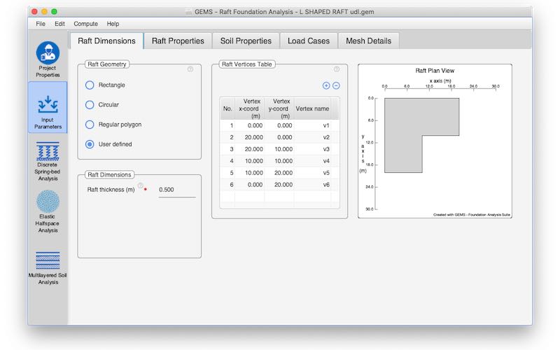
Rafts with different geometries (Rectangular, circular, regular polygon, user-defined) can be considered.
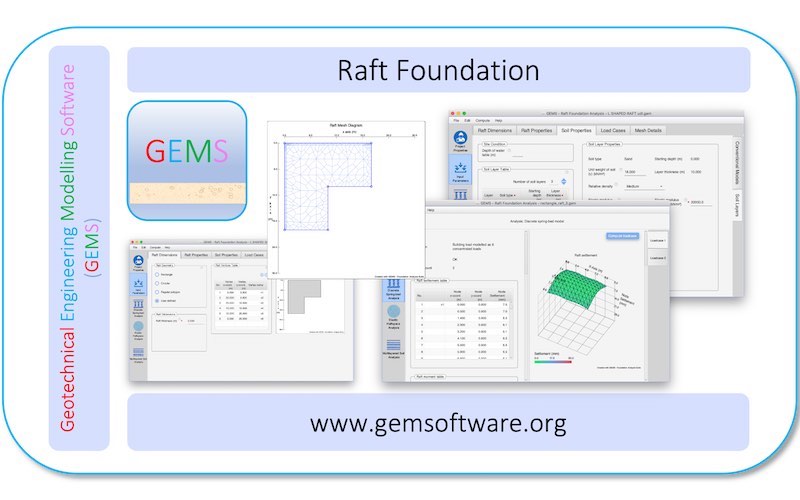
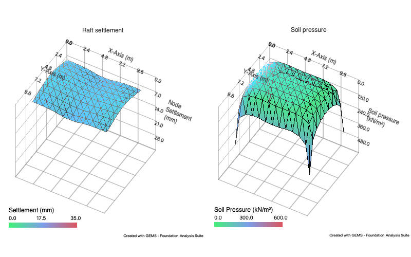
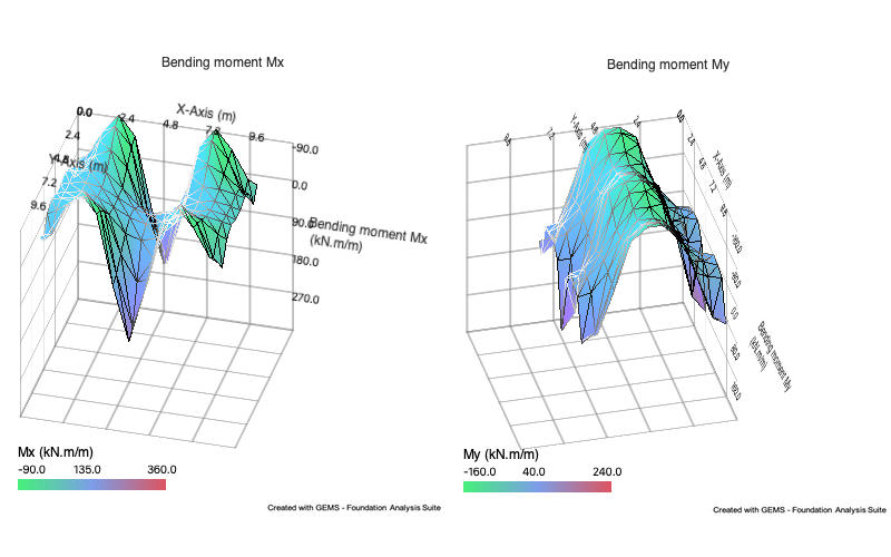
At GEMS (Geotechnical Engineering Modelling Software), we specialize in providing advanced solutions for the analysis and design of raft foundations. Our software is designed to streamline the complex process of geotechnical engineering, enabling engineers to work more efficiently and effectively. With GEMS, you can confidently tackle the challenges of foundation analysis and design, ensuring the structural integrity and stability of your projects.
Rafts with different geometries (Rectangular, circular, regular polygon, user-defined) can be considered.
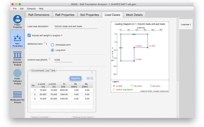
Multiple loading scenarios could be defined.
The loading may consist of several concentrated loads & moments applied at various points on the raft
Multiple line loads can be applied on the raft.
Multiple uniform loads applied over different areas on the raft can be specified.
Self-weight may be included if required.
Immediate term and long-term settlement can be determined for multi-layered soil model.
No-contact tension analysis is automatically performed by the software by an iterative procedure.
Automatic mesh generation taking all input parameters into account
Graphical representation of the raft along with finite element grid used for computation.
Graphical representation of loading for each case.
One click computation and analysis for all load cases and models.
Export results to MS Word, Excel and PDF
Data can be input in either SI units or ‘Commonly used American units’ (kips for force and foot for length).
Supported on Windows, Mac and Cloud
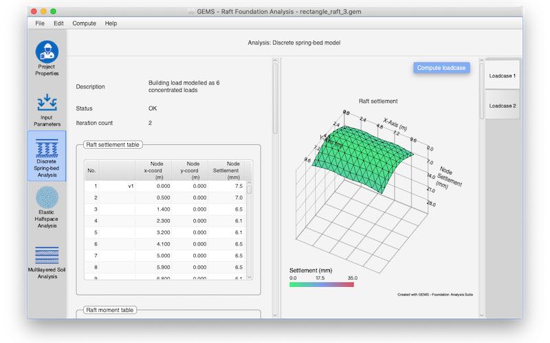
Analysis results include tabular & graphical representation of
a. Raft settlement
b.
Bending & twisting moment
c. Shear
forces
d. Soil pressure
The GEMS Raft Foundation software utilizes cutting-edge finite element modelling techniques, ensuring accurate analysis and design. The analysis is carried out by idealizing the raft as an elastic plate of finite rigidity resting on soil sub grade. Our software offers multiple models for idealizing the soil support, including:
The settlement and bending behaviour of a raft depends significantly on its thickness and the nature of soil support. The differential equation governing the flexture of a thin raft is

 is the
flextural rigidity of the plate.
When the raft gets thicker the governing equations become much more complex. Hence for practical problems analytical solution will be impractical and recourse has to be taken to numerical solution.
Here, GEMS shines with its implementation of finite element modelling based on Mindlin’s plate theory. The raft foundation is discretized into number of bilinear quadrilateral plate elements, with each of its node having three degrees of freedom, vertical displacement and rotations about x and y axis sufficient to represent the deformed shape of the raft. Our software facilitates the consideration of thick or thin plates of various geometric configurations, load scenarios, and soil-structure interactions. Concentrated vertical loads and moments, line loads, and distributed vertical loads can be imposed on the raft. Different soil support models could be combined with the raft and the integrated system analysed considering effects of soil- structure interaction. Furthermore, automatic mesh generation capabilities simplify usage, ensuring seamless integration into engineering workflows while delivering accurate and reliable results.
With GEMS Raft Foundation analysis software, engineers are equipped to conquer the complexities of foundation analysis and design, empowering them to realize their vision for safe, resilient, and sustainable structures.
Finite element formulation is used in which raft is divided in to a number of quadrilateral plate elements. Division into quadrilateral elements enables raft of different shapes - rectangular, circular, polygonal, user-defined to be considered. The soil support stiffness is obtained based on the selected soil model. Both structural and soil stiffness are combined to obtain the overall stiffness of the system. The equilibrium equations are then solved where the knowns are the applied loads and the unknowns are the raft displacements.
Analysis and design of a raft foundation involves consideration of flexural rigidity of the raft and nature of sub-soil profile at the site. The raft is modelled as a plate in structural analysis. Raft foundation transfers stresses to greater depths in soil and the deformation properties of soil with in the zone of influence need to be considered. Below mentioned three types of soil support models are supported by the software.
In the discrete spring-bed model, the soil support is idealized as a linear spring bed. The stiffness of the soil support is characterized by the equation ps=ksw , where ks represents the modulus of subgrade reaction. This model, also known as the Winkler model, does not fully account for the continuity present in the soil mass. Due to the extended stressed zone beneath the raft, selecting a representative value for ks is necessary.
In this approach the subsoil is replaced by a homogeneous, isotropic elastic half-space characterised by an elastic modulus and a Poisson ratio. This model considers the continuous nature of the soil medium and determines the soil support stiffness based on Boussinesq’s equation for vertical displacement. Similarly, due to the deep stressed zone beneath the raft, choosing representative values for the Young’s modulus and Poisson ratio for the underlying soil becomes imperative.
Raft foundations transfer stresses to greater depths within the soil, necessitating the consideration of deformation properties of all soil layers within the zone of influence. The ‘Multi-layer soil model’ is based on the sub-surface soil profile at the location and utilizes data obtained from comprehensive field and laboratory investigations.
The settlements may be expressed as

For elastic behaviour εz is calculated as:
Sand and rock layers are modelled by using appropriate values of elastic modulus and Poisson ratio for each layer.
In clay layers immediate behaviour is modelled by using un-drained elastic modulus Eu and un-drained Poisson ratio vu=0.5. The long term behaviour in clay layers is modelled by using the following conventional equation
εz = mv𝜎zIn which mv is coefficient of volume compressibility of the clay and 𝜎z is the increase in the vertical stress. The settlement can then be computed by summation across all layers (n):

Copyright © All Rights Reserved