One Click Computation
One click computation for pile capacity, design load estimation and pile group settlement
Piles are often used in groups to carry greater loads to deeper, stronger soil strata. For the same average load per pile, groups settle more than single piles due to overlapping of deformations in the soil medium.
The 'GEMS – Pile Group Settlement Analysis' software uses modern analytical techniques based on the subsurface soil profile, pile dimensions and group geometry to estimate the pile group settlement. The software can also be used to choose pile length, cross-section, and pile spacing towards optimizing the group design.
One click computation for pile capacity, design load estimation and pile group settlement
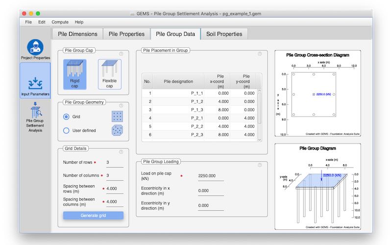
Rigid cap & Flexible cap piles can be analysed.
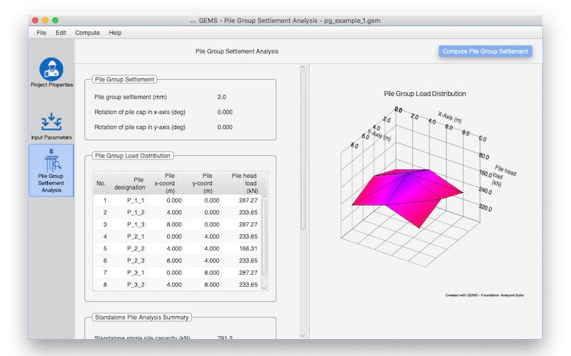
Group settlement, pile cap rotation and individual pile loading for pile group with rigid cap. 3D graphical representation of pile loading.
Axial single pile capacity & design load estimation
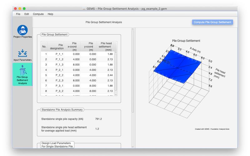
Individual pile settlement for pile group with flexible cap. 3D graphical representation of pile settlement.
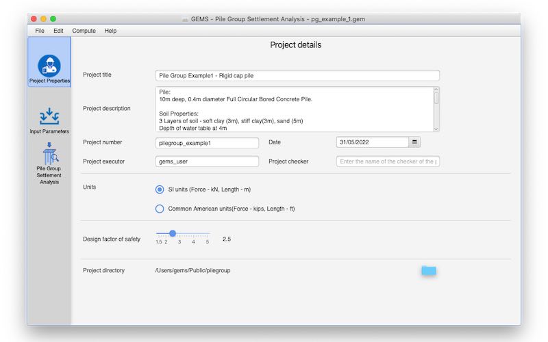
Data can be input in either SI units or ‘Commonly used American units’ (Kips for force and foot for length)
Single pile settlement under design load
3D representation of the pile group
Pile group cross-section diagram
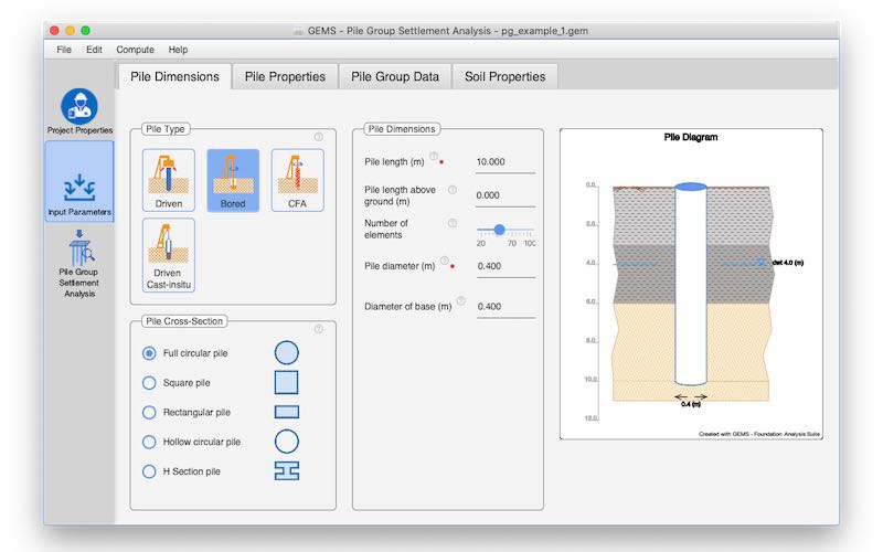
Pictorial representation of the pile and soil layers.
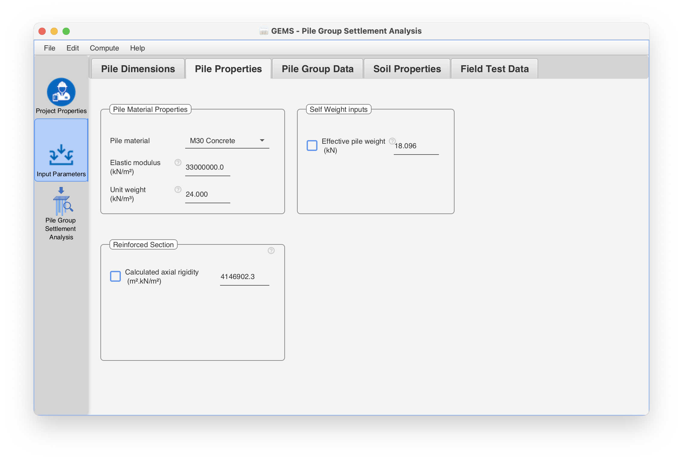
User can prescribe axial rigidity of pile to take reinforcement of pile into account
Local scour and ground water table consideration
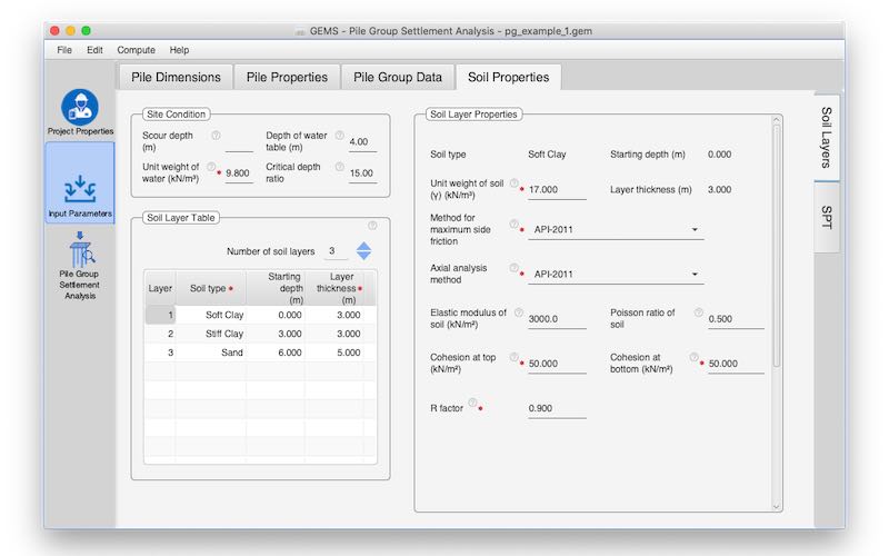
Clay, sand, rock layers can be specified
Facility to use load test results instead of layerwise soil properties
Export results to Microsoft Word, Excel & PDF
Support for Windows, Mac
Available on cloud using a browser
Linear & Non-linear analysis models
The vertical movement in soil medium surrounding a single pile loaded vertically decreases gradually from the pile shaft in the radial direction. Considering soil to be elastic, 'shear stress decrease' to be only in the radial direction, and following concentric cylindrical assumption, Randolph and Wroth (1978) showed that the decrease in vertical displacement is logarithmic and extends to a radial distance rm of the order of pile length. Further using rigid circular punch model for the tip settlement, and considering axial pile stiffness they derived settlement expression for a single pile under axial load.
A loaded vertical pile has a deformation field around it. Similarly loaded adjacent piles in a group also have their own deformation fields. Superposition of the deformation fields of piles in a group renders piles in a group to settle more than a single pile.
Apart from the behaviour of single pile, this superposition effect depends on the number piles, spacing of piles in the group and the rigidity of the cap connecting them. Usually the group settlement is required under a total load approximately equal to n×Pd where n is the number of piles in the group and Pd is the design load. Group geometry and the behaviour of single pile under the design load are required for the group settlement estimate.
If the piles are connected at the head by a relatively flexible cap, there will be no transfer of loads through the cap and each pile will experience the load imposed on it. The group deflection will depend on the load distribution among piles. The software provides for
When the piles are connected by a rigid cap, all the loads imposed on the cap may be combined in to a resultant vertical load. The resultant load may be centric or may be eccentric with respect to the centroid of the group. If the loading is centric, the cap redistributes the load among piles so as to result in uniform group settlement. Due to the redistribution, the edge piles will carry greater load than the central piles.
In the case of eccentric loading two requirements need to be met. Firstly the loads carried by piles need to satisfy vertical and moment equilibrium requirements of the group. Secondly the distribution of loads should result in a planar settlement profile of the cap comprising a vertical settlement of the centroid of the group sg along with two rotations θx and θy rotations about x and y axis respectively.
Using a special stiffness formulation, the software computes the settlement the centroid of the group, rotations θx and θy and the individual pile loads.
The Piles of circular, square, rectangular, circular-hollow and I or H cross sections can be analyzed. Piles of different types of cross-sections are approximated to a circular pile of an equivalent diameter for analysis.
 |
 |
 |
 |
 |
|---|---|---|---|---|
| Circular | Square | Rectangular | Hollow-Circular | I or H Section |
Bored piles (Cast-insitu-concrete) and driven piles (Precast concrete, Cast-insitu-concrete, Steel) can also be analyzed.
The software can take into account layered soil profiles which may consist of soft clay, stiff clay, sand, soft rock, hard rock layers. Soil scour around the piles and pile lengths projecting above the ground can be specified. These provisions are especially useful in analysing piles used in foundations of bridges and waterfront structures. Depth of ground water table in the subsoil can also be considered for land based piles.
Under the design load, the pile behaviour will be nearly elastic except for some shaft length near the top of the pile, where the ultimate interface friction may be reached and the pile may slide through soil. The parameters that are required for the group settlement estimate under the design load are the pile head displacement, load carried by the pile tip, pile tip displacement and the radius rm which may be approximated as equal to pile length. The software makes use of Randolph and Wroth (1978) approach along with Mylonakis and Gazetas (1998) procedure for including the diffraction effect.
A three step approach is followed to obtain the group vertical settlement.
The pile capacity estimation is based on the sub-soil layer properties and the methods chosen for the assessment of shaft friction and base capacity. The design load is computed from the pile capacity taking into account the design factor of safety.
Procedures available in the software for pile capacity estimation
| Clay | Sand | Rock |
|---|---|---|
| Side Friction | ||
|
|
|
| Base Capacity | ||
|
|
|
There are options available in the software to prescribe user defined parameters.
A distance of 3D is used for developing full base resistance in strong layers. A safe distance of from pile tip of 3D is adopted to preclude punch through underlying weak layers.
The Axial pile deformation analysis is performed to determine the pile head and pile tip stiffness under the design load.
Pile is modelled as an elastic structural member having the cross section of the pile and the elastic properties of the pile material. The soil support providing the shaft friction is modelled by a set of side springs based on t-z curves. The tip resistance provided by the pile base the base is modelled by a spring based on q-z curve.
The software supports both ‘Elastic Bi-linear’ and ‘Non-Linear’ approaches for modelling the soil layers and any one of them can be selected for analysis.
In the ‘Non-Linear’ approach’ for the soil layer, based on the tmax and qmax values calculated , non-linear t-z curves (interface shear stress- vertical pile movement at that point) and q-z curve (bearing stress and toe displacement) are developed based on API-2011 guidelines. API based methods, also account for reduction in post peak adhesion in clay layers through a factor R.
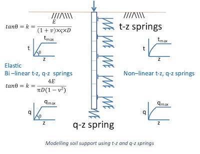
In the ‘Elastic Bi-linear’ approach, for the soil layer, t-z and q-z relationships are modelled by bilinear elastic – plastic curves based on the elastic modulus, Poisson ratio, tmax and qmax for the layer.
In the case of rock layers, using the tmax and qmax values, t-z and q-z relationships are modelled by a bilinear elastic – plastic curve based on the elastic modulus and Poisson ratio of the rock layer.
The axial pile analysis follows a non-linear finite element model using the axial rigidity of the pile and the nonlinear soil support based on the t-z curves and q-z curve. . The analysis uses an Iterative approach to achieve convergence.
The analysis provides displacement of the pile head and pile tip under design load, and the load transferred at the pile base.
Copyright © All Rights Reserved