Comprehensive Pile Foundation Analysis (Land, Bridge & Waterfront Structures)
Overview
Piles are used to provide foundation support to wide ranging
structures such as buildings, bridges, wharves, jetties and towers. Piles may
be broadly classified into several types as shown below.
|
Pile types
|
|
Based on soil
displaced
|
Displacement
|
Part displacement
|
Non- displacement
|
|
Based on pile
material & method of construction
|
Driven
|
Driven
|
Bored
|
|
Precast concrete
|
Cast-insitu-concrete
|
Precast concrete
|
Steel
|
Cast-insitu-concrete
|
|
Square or rectangular
|
Circular
|
Hollow cylindrical
|
Tubular
|
H-section
|
Circular
|
With enlarged base
|
CFA
|
|
|
|
|
|
|
|
|
|
The choice of the pile type is governed by sub-soil strata,
ground water conditions, its chemical composition, facility of construction,
local experience, available technology and cost.
The loading on piles can be in axial direction (compressive
or tensile) and in lateral direction (shear and moment). The loading may be
due to self-weight of structures, live loads, wind and earthquake forces. In
water front-structures forces due to ship impact and mooring forces will
require consideration. In bridge piles, scour around piers needs to be taken in
to account. Abutment piles will also be subject to lateral earth pressure. In
many instances axial and lateral forces will act above the ground level
requiring consideration of beam column action. In all cases the piles designed
should meet the serviceability and safety requirements under all loading
conditions.
The pile analysis software is developed keeping in view all
the above requirements.
This software offers is a single
platform consideration of different pile types, different codes of practice as
well as other well-known procedures adopted in practice.
This pile analysis software can be used in several ways
towards achieving design requirements:
·
Based on sub-soil properties and pile parameters, analyse the
pile for different loading scenarios.
·
Perform analysis towards optimizing pile length and size.
·
Evaluating performance of different types of piles in making a
choice.
·
It may be used in comparing results of load tests with the
results of analysis and in fine tuning pile design parameters.
The ‘Comprehensive Pile Foundation Analysis (Land, Bridge
& Waterfront Structures)’ software of GEMS provides advanced and intuitive modules for the
all the above analysis.
There are three modules available
The Piles of circular, square, rectangular, circular-hollow
and I or H cross sections can be analysed. Bored piles (Cast-insitu-concrete)
and driven piles (Precast concrete, Cast-insitu-concrete, Steel) can also be
analysed.
|

|

|

|

|

|
|
Circular
|
Square
|
Rectangular
|
Hollow circular
|
I or H Section
|
Soil scour around the piles and pile lengths projecting
above the ground can be specified. These provisions are especially useful in
analysing piles used in foundations of bridges and waterfront structures. Depth
of ground water table in the subsoil can also be considered.
Key Features
|
· One click computation and analysis for all load
cases and modules.
· Piles of circular, square, rectangular,
circular-tubular & I or H cross sections can be analysed.
· Axial pile capacity estimation
· Analysis of the pile foundation under combined
lateral and axial loads.
· Linear & Non-linear analysis models
· Multiple load cases.
· Pictorial representation of the pile and soil layers.
· Loading diagrams for each load case.
·
Export of results to Microsoft Word, Excel & PDF
·
Supported on Windows, Mac and Cloud
· Data can be input in either SI units or ‘Commonly
used American units’ (kips for force and foot for length)
|
· Self-weight of pile may be included if required.
· Multiple axial, lateral loads and lateral moments
can be specified along the length of the pile at various depths (up to 20
including pile head) for each load case.
· Distributed lateral load (triangular, uniform, or
trapezoidal) can be given.
· Static and cyclic loadings can be incorporated for
lateral analysis.
· Local scour & ground water table considerations.
· Facility of prescribing lateral displacement,
rotation & rotational spring at the pile head.
· Can consider reinforcement parameters.
· Generation of p-y, t-z and Q-z curves based on soil
properties.
· Handy tool for resolving forces.
|
Pile
Capacity Estimation
The ultimate axial capacity under compressive or tensile
load is computed based on the soil layer properties. The software gives the
pile capacity at various depths of soil and also breaks it down to its
contributing factors viz. shaft friction and base capacity. The pile capacity
estimation is based on the sub-soil layer properties and different methods for
assessment of shaft friction and base capacity. Presently the below methods of
analysis are available:
|
Clay
|
Sand
|
Rock
|
|
Side
Friction
|
Base
capacity
|
|
|
· API-2011
· α method (IS-2911)
· Semple & Rigden method
· Kolk & Van-der-velde method
|
· β
method (API-2011)
· K-δ method (API-2000)
· K-δ-Zc method (IS-2911)
· Meyeroff SPT method (IS-2911)
|
· Nq-qlim method (API-2011, API-2000)
· Nq - Zc method (IS-2911)
· Nq-Berezantev-Zc method
· Meyeroff SPT method (IS-2911)
|
· Approach based on unconfined strength is adopted
|
A distance of 3D is used for developing full base resistance
in strong layers. A safe distance of 3D from pile tip is adopted to preclude
punch through underlying weak layers. For rock layers an approach based on
unconfined strength is adopted.
Axially Loaded Pile Analysis
Axial pile deformation analysis
Pile is modelled as an elastic
structural member having the cross section of the pile and the elastic
properties of the pile material. The soil support providing the shaft friction
is modelled by a set of side springs based on t-z curves. The tip resistance
provided by the pile base the base is modelled by a spring based on Q-z curve.
The following loading may be given and used for the analysis
a) Axial
loads at various depths along the length of the pile (up to 20 including load
at pile head).
b) Self-weight of
the pile
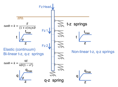
 The software supports both ‘Elastic (continuum) Bi-linear’
and ‘Non-Linear’ approaches for modelling and any one of them can be selected
for analysis.
The software supports both ‘Elastic (continuum) Bi-linear’
and ‘Non-Linear’ approaches for modelling and any one of them can be selected
for analysis.
Modelling
soil support using t-z and q-z springs
In the ‘Non-Linear’
approach, for the soil layer, based on the tmax and qmax
values calculated , non-linear t-z curves (interface shear stress- vertical
pile movement at that point) and q-z curve (bearing stress and toe
displacement) are developed based on API-2011 guidelines.
In the ‘Elastic (continuum)
Bi-linear’ approach, for the soil layer, t-z and q-z relationships are modelled
by bilinear elastic – plastic curves based on the elastic modulus, Poisson
ratio ,tmax and qmax for the layer.
The axial pile analysis
follows a non-linear finite element model using the axial rigidity of the pile
and the nonlinear soil support based on the t-z curves and q-z curve. The
analysis uses an Iterative approach to achieve
convergence.
The analysis provides settlement
of the pile head under a given load on the pile, variation of axial load along
the pile length, and the load carried by the pile base. Different loads applied
on the pile head and the corresponding head settlements provide the load settlement
curve.
Generation of t-z and Q-z curves
Development of a set of t-z curves along the shaft length
and Q-z curve at the pile base for compressive loading. Multiple t-z curves
are generated for each soil layer. The below methods are available for
generation of the t-z for each layer and Q-z curves at the pile base.
|
Soft Clay
|
Stiff Clay
|
Sand
|
Weak Rock
|
Hard Rock
|
|
· API-2011
· API-2000
· Elastic
Method
|
· API-2011
· API-2000
· Elastic
Method
|
· API-2011
· API-2000
· Elastic
Method
|
· Elastic Method
|
· Elastic Method
|
API based methods, also account for reduction in post peak
adhesion in clay layers through a factor R.
Laterally Loaded Pile Analysis
Lateral pile deflection analysis.
Analysis of a pile subjected to lateral load and moment is
carried out in this module. Finite element based approach is adopted to model
the pile and the soil support in which the pile is divided in to a number of
elastic beam bending elements. The method allows consideration of inhomogeneous
and non-linear modelling of soil support. The lateral soil support for the pile
is modelled by the well-known p-y springs.
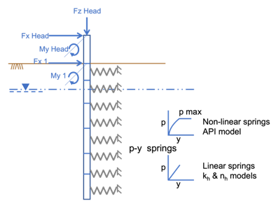
Modelling
soil support using p-y springs
The following loading may be given and used for the analysis
a) Lateral loads, lateral moments and axial loads can be
specified along the length of the pile at various depths (up to 20 including
pile head) for each load case. The axial load applied at the pile head
will be considered for taking the beam-column effect into account.
b) Distributed
lateral load for a section along the pile length. Loading can be triangular, uniform,
or trapezoidal.
The following boundary conditions may be given at the pile
head
a)
Prescribed lateral displacement
b)
Prescribed rotation
c)
Prescribed rotational stiffness.
For pile having free head condition both lateral load and
moment can be prescribed at the pile head. The method can consider the effect
of axial loading at the pile head due to beam column action in lateral pile
analysis. The pile head can project above the ground.
The finite element discretization not only takes in to
account the specified pile make-up but is also optimized for better accuracy.
An iterative procedure based on secant modulus approach is used for
convergence.
Generation of p-y curves.
In this module p-y curves are generated for the soil layers
based on their properties. Multiple p-y curves are generated for each layer. The
below methods are available for generation of p-y curves based on soil type.
|
Soft Clay
|
Stiff Clay
|
Sand
|
Weak Rock
|
Hard Rock
|
|
· API-2011
· Kh
based horizontal subgrade modulus
· Nh
based horizontal subgrade modulus
|
· API-2011
· REESE
· Kh
based horizontal subgrade modulus
|
· API-2011
· Nh
based horizontal subgrade modulus
· Hybrid model
for liquified sand (Based on friction angle)
· Hybrid model
for liquified sand (Based on SPT)
|
· REESE
· Kh
based horizontal subgrade modulus
|
· Turner (2006)
· Kh
based horizontal subgrade modulus
|


